用 Three.js 造一辆自行车:先算几何,再画模型 Building a Bicycle in Three.js: Geometry Before Meshes
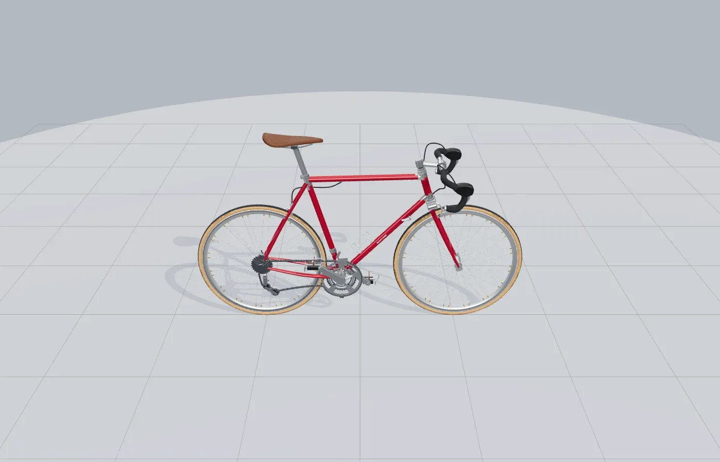
自行车适合用代码建模。它的外形不是一堆零件碰巧摆在一起:轴距决定前后轮,后下叉决定五通,头管角和前倾量决定前叉。把这些关系写成数学,Three.js 只需要负责把结果画出来。
这辆车没有导入模型。车架、轮圈、辐条、链条,连刹车线都是 Three.js 几何体。完整源码在 Makone,下面只摘出每一步真正用到的部分。
最初的版本从两个圆和几根 CylinderGeometry 开始。十分钟后,侧面已经像一辆车;镜头转到正面,轮子却不在一条线上,前叉也穿进了花鼓。尺寸散落在几十个 position.set() 里,彼此没有关系。
解决办法是把顺序倒过来:先算点,后画形。
先把自行车写成一组点
场景单位统一用米。后轴是原点,轴线高度等于车轮滚动半径;前轴只由轴距决定。五通的位置也不用目测,它由后下叉长度和五通下沉量解出来。
const GEO = {
  wheelbase: 1.005,
  drop: 0.070,
  chainstay: 0.412,
  headAngle: 73,
  rake: 0.047,
  forkLen: 0.372,
};

const P = {};
P.rearAxle = [0, wheelR];
P.frontAxle = [GEO.wheelbase, wheelR];
P.bbY = wheelR - GEO.drop;
P.bbX = Math.sqrt(GEO.chainstay ** 2 - GEO.drop ** 2);
P.bb = [P.bbX, P.bbY];

const a = THREE.MathUtils.degToRad(GEO.headAngle);
const axisUp = [-Math.cos(a), Math.sin(a)];
const rakeDir = [Math.sin(a), Math.cos(a)];
P.crown = [
  P.frontAxle[0] + axisUp[0] * GEO.forkLen - rakeDir[0] * GEO.rake,
  P.frontAxle[1] + axisUp[1] * GEO.forkLen - rakeDir[1] * GEO.rake,
];
这些点是模型的接口。车架读 P.bb,曲柄也读 P.bb;轮子、飞轮和后拨都读 P.rearAxle。改轴距时,零件一起走,不会留下一个仍停在旧坐标上的刹车夹器。
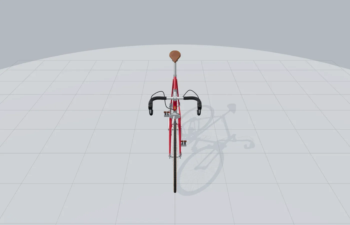
正面是很残酷的检查角度。侧面看着像车的模型,到了这里往往会露出所有随手偏移。
一根管只接受两个端点
车架的基本工件不是“横梁”或“斜梁”,只是一根从 A 到 B 的管。圆柱默认沿 Y 轴生成,所以先算方向和中点,再把它转过去。
function tubeBetween(a, b, r0, r1 = r0, segments = 16) {
  const A = new THREE.Vector3(...a);
  const B = new THREE.Vector3(...b);
  const dir = B.clone().sub(A);
  const mid = A.clone().addScaledVector(dir, 0.5);

  const geometry = new THREE.CylinderGeometry(
    r1, r0, dir.length(), segments, 1, false
  );
  geometry.applyQuaternion(
    new THREE.Quaternion().setFromUnitVectors(
      new THREE.Vector3(0, 1, 0), dir.clone().normalize()
    )
  );
  geometry.translate(mid.x, mid.y, mid.z);
  return geometry;
}

painted.push(
  tubeBetween(P.headBottom, P.headTop, 0.0175),
  tubeBetween(P.topAtSeat, P.topAtHead, 0.0143, 0.0136),
  tubeBetween(P.bb, P.downAtHead, 0.0159, 0.0146),
  tubeBetween(P.bb, P.seatTop, 0.0143),
);后下叉和前叉略有弯曲,TubeGeometry 沿三四个控制点扫掠,并沿路径逐段缩小半径。细节可以晚一点再加。先把模型转到四个方位,只看轮廓、离地间隙和零件是否相撞。
五组组件,使用同一套安装点
这辆车分成 frame、wheel、drivetrain、cockpit 和 cables。拆分的标准很简单:现实里能从车上拆下来的东西,在代码里也应该能单独构建。它们没有各自猜一套位置,而是共同读取 params.js 里的 P。五通、后轴、头管顶端和刹车座都只有一个答案。
const bike = new THREE.Group();
bike.add(buildFrame(), buildDrivetrain(), buildCockpit(), buildCables());

const rear = buildWheel();
const front = buildWheel();
front.position.x = GEO.wheelbase;
bike.add(rear, front);

// 模型由后轴向前搭,完成后再把整体移到展台中央。
bike.position.x = -GEO.wheelbase / 2;
scene.add(bike);
车架:管材之间不是“大概接上”
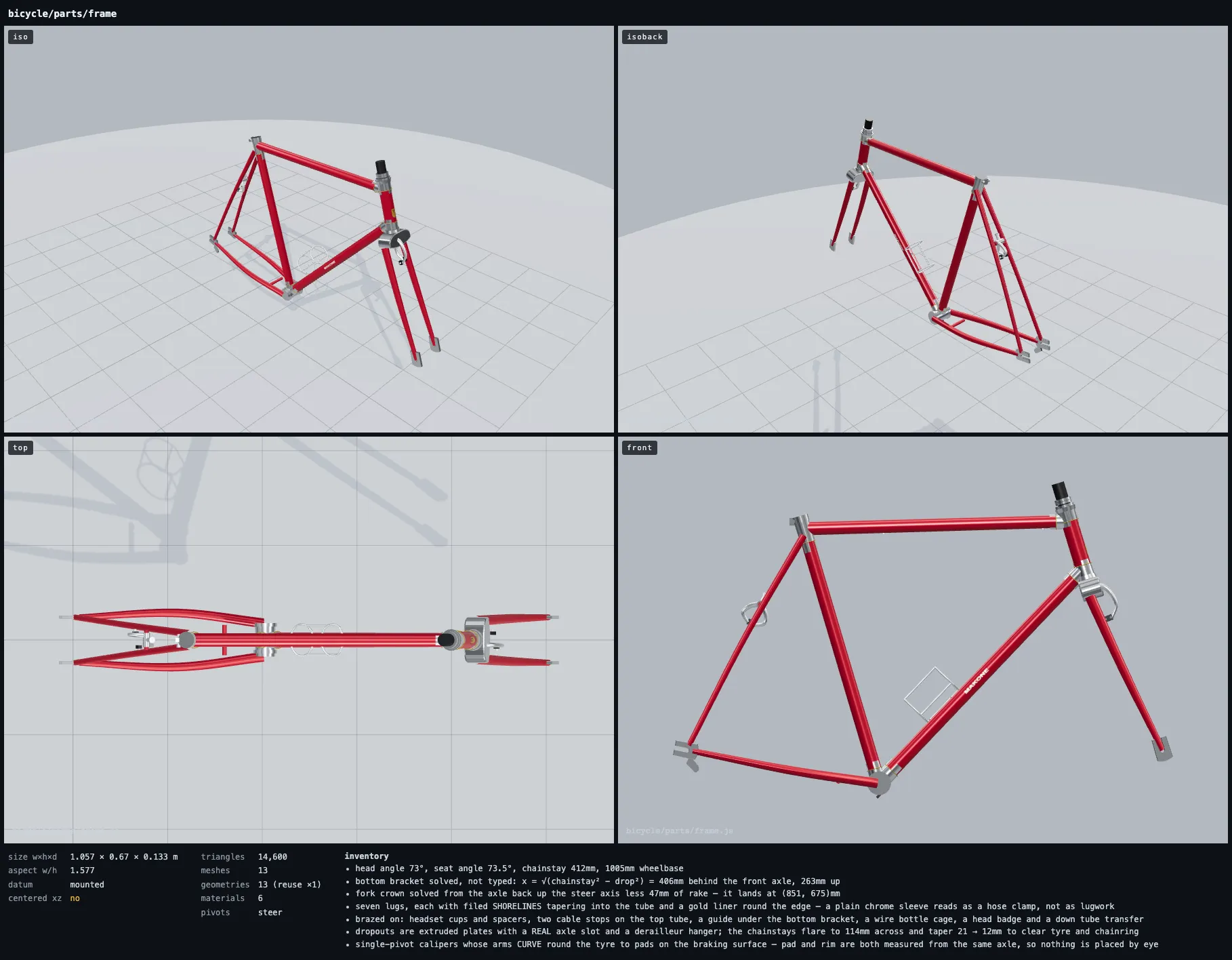
车架单独放出来以后,前叉的弯曲、后叉的开度和两只刹车的位置都无处可藏。
主三角的每根管都连接两个已经解出的点。后叉则需要绕开轮胎和牙盘,所以用三段控制点做出外扩和收窄。最后,同材质的几何体合并成一个 mesh;细小的接头、线管座和金属件不会各占一次 draw call。
const V = (xy, z = 0) => [xy[0], xy[1], z];
const painted = [], chrome = [], liners = [], blacks = [];

painted.push(
  tubeGeo(V(P.headBottom), V(P.headTop), p.tubeHead, p.tubeHead, 20),
  tubeGeo(V(P.topAtSeat), V(P.topAtHead), p.tubeTop, p.tubeTop * 0.95, 18),
  tubeGeo(V(P.bb), V(P.downAtHead), p.tubeDown, p.tubeDown * 0.92, 18),
  tubeGeo(V(P.bb), V(P.seatTop), p.tubeSeat, p.tubeSeat, 18),
);

for (const [geos, mat, parent] of [
  [painted, paint, g], [chrome, chromeMat, g],
  [liners, gold, g], [blacks, dark, g],
]) {
  const mesh = new THREE.Mesh(merge(geos), mat);
  mesh.castShadow = mesh.receiveShadow = true;
  parent.add(mesh);
}
轮组:构建两次,几何只生成一次
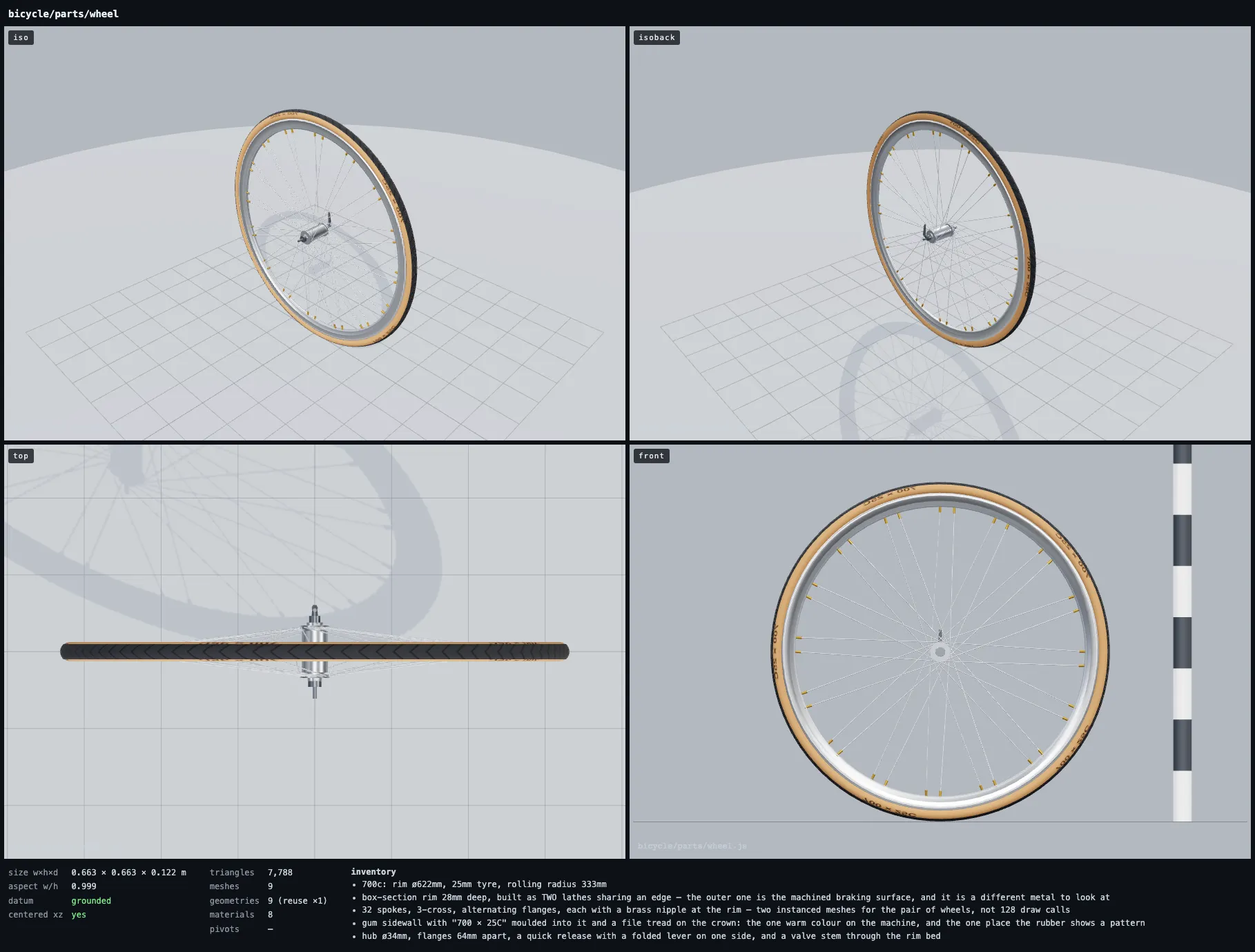
轮组从正面读辐条,从顶部查轮圈、花鼓和轮胎是不是共享一条轴线。
buildWheel() 会被调用两次,但轮圈、轮胎、花鼓和辐条数据缓存在模块里。前后轮共享 buffer,只保留各自的位置和旋转。辐条矩阵交给 InstancedMesh,否则两只轮子上的细线会变成一长串独立 mesh。
let CACHE = null;

function geos(p) {
  if (CACHE) return CACHE;
  const rIn = p.rimR - p.rimDepth;
  const rOut = p.rimR;
  const halfWidth = p.rimW / 2;
  const V = (r, y) => new THREE.Vector2(r, y);

  const body = [
    V(rOut - 0.0165, -halfWidth * 0.84),
    V(rIn + 0.0030, -halfWidth * 0.30),
    V(rIn, -halfWidth * 0.42),
    V(rIn, halfWidth * 0.42),
    V(rIn + 0.0030, halfWidth * 0.30),
    V(rOut - 0.0165, halfWidth * 0.84),
  ];

  CACHE = {
    body: new THREE.LatheGeometry(body, 72).rotateX(Math.PI / 2),
    tyre: new THREE.TorusGeometry(p.rimR + p.tyreR * 0.62, p.tyreR, 16, 96),
    lace: lacing(p),
  };
  return CACHE;
}

const G = geos(p);
wheel.add(
  new THREE.Mesh(G.body, materials.rim),
  new THREE.Mesh(G.tyre, materials.gum),
  instanced(G.lace.spokes, materials.spoke),
  instanced(G.lace.nipples, materials.brass),
);
传动:先画出机械轮廓,再让它转
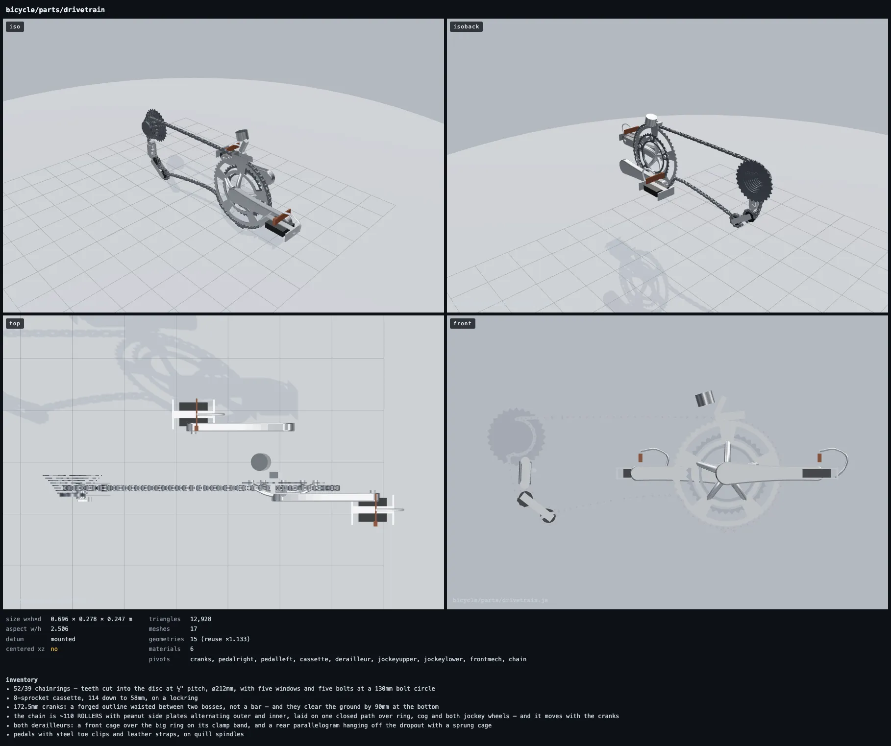
传动侧最容易看起来像一团金属;把组件拿出来,牙盘、链线和后拨的层次才看得清。
牙盘不是一个贴着齿纹的圆盘。外圈按链轮齿数交替取半径,中间挖出轴孔和窗口,再用 ExtrudeGeometry 给它厚度。这样五爪盘片、齿和链条在近处仍然是不同的结构。
function ringGeo(rOuter, teeth, thickness, { rBore, windows = 5 }) {
  const shape = new THREE.Shape();
  const toothDepth = Math.min(rOuter * 0.10, ((Math.PI * rOuter) / teeth) * 0.9);

  for (let i = 0; i < teeth * 2; i++) {
    const angle = (i / (teeth * 2)) * Math.PI * 2;
    const radius = i % 2 ? rOuter - toothDepth : rOuter;
    const [x, y] = [Math.cos(angle) * radius, Math.sin(angle) * radius];
    if (i) shape.lineTo(x, y); else shape.moveTo(x, y);
  }
  shape.closePath();

  const bore = new THREE.Path();
  bore.absarc(0, 0, rBore, 0, Math.PI * 2, true);
  shape.holes.push(bore);

  const r0 = rBore + (rOuter - toothDepth - rBore) * 0.20;
  const r1 = rBore + (rOuter - toothDepth - rBore) * 0.82;
  for (let i = 0; i < windows; i++) {
    const centre = (i / windows) * Math.PI * 2 + 0.30 + Math.PI / windows;
    const half = (Math.PI / windows) * 0.72;
    const window = new THREE.Path();
    window.absarc(0, 0, r1, centre - half, centre + half, false);
    window.absarc(0, 0, r0, centre + half, centre - half, true);
    shape.holes.push(window);
  }

  return new THREE.ExtrudeGeometry(shape, {
    depth: thickness,
    bevelEnabled: false,
  });
}
座舱:把横和把带必须共用一条曲线
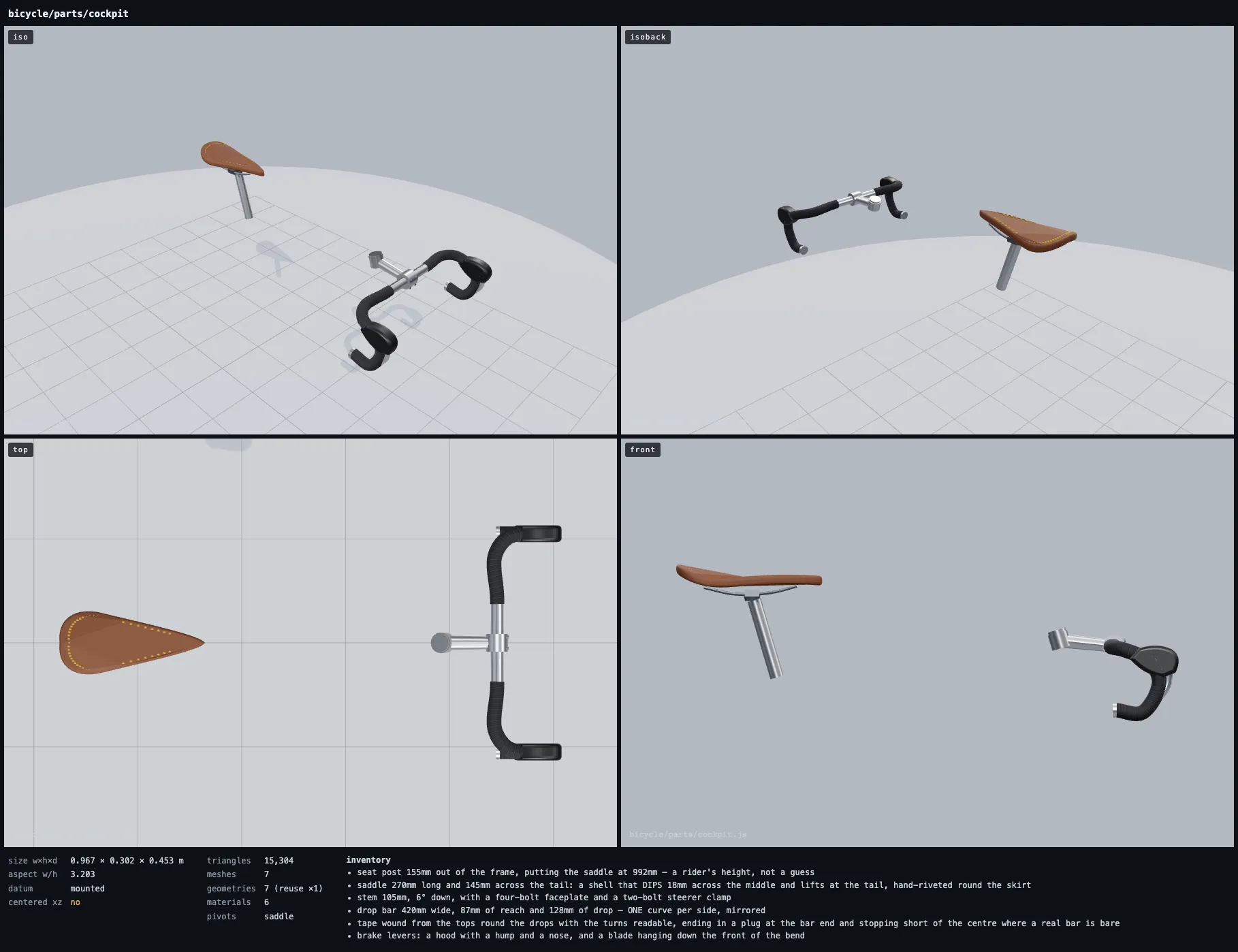
坐垫和弯把离车架很远,任何偏心都会直接改变整辆车的姿态。
弯把左右镜像,每一侧由一串控制点定义。把带不能再拟合一条“差不多”的曲线,否则转弯处会钻进金属。这里先把弯把路径密集采样,再从同一组点截出需要缠带的部分。
const [bx, by] = P.barCentre;
const half = p.barW / 2;

for (const sz of [-1, 1]) {
  const points = [
    [bx, by, 0],
    [bx, by, sz * half * 0.42],
    [bx - 0.004, by - 0.002, sz * half * 0.80],
    [bx + 0.022, by - 0.008, sz * half * 0.97],
    [P.hoodAt[0], P.hoodAt[1], sz * half],
    [bx + p.barReach, by - p.barDrop * 0.55, sz * half],
    [bx + p.barReach * 0.62, by - p.barDrop, sz * half],
    [bx + p.barReach * 0.04, by - p.barDrop * 0.96, sz * half],
  ];

  const spine = new THREE.CatmullRomCurve3(
    points.map((q) => new THREE.Vector3(...q)), false, 'centripetal',
  ).getSpacedPoints(64);

  bright.push(taperedTubeGeo(spine,
    [p.barR * 1.06, p.barR * 1.02, p.barR, p.barR, p.barR, p.barR, p.barR, p.barR],
    { seg: 52, radial: 12 }));
  taped.push(taperedTubeGeo(spine.slice(11),
    [p.barR + 0.0020, p.barR + 0.0026, p.barR + 0.0026,
      p.barR + 0.0026, p.barR + 0.0026, p.barR + 0.0022],
    { seg: 54, radial: 14 }));
}
线缆:连接的是已经存在的零件
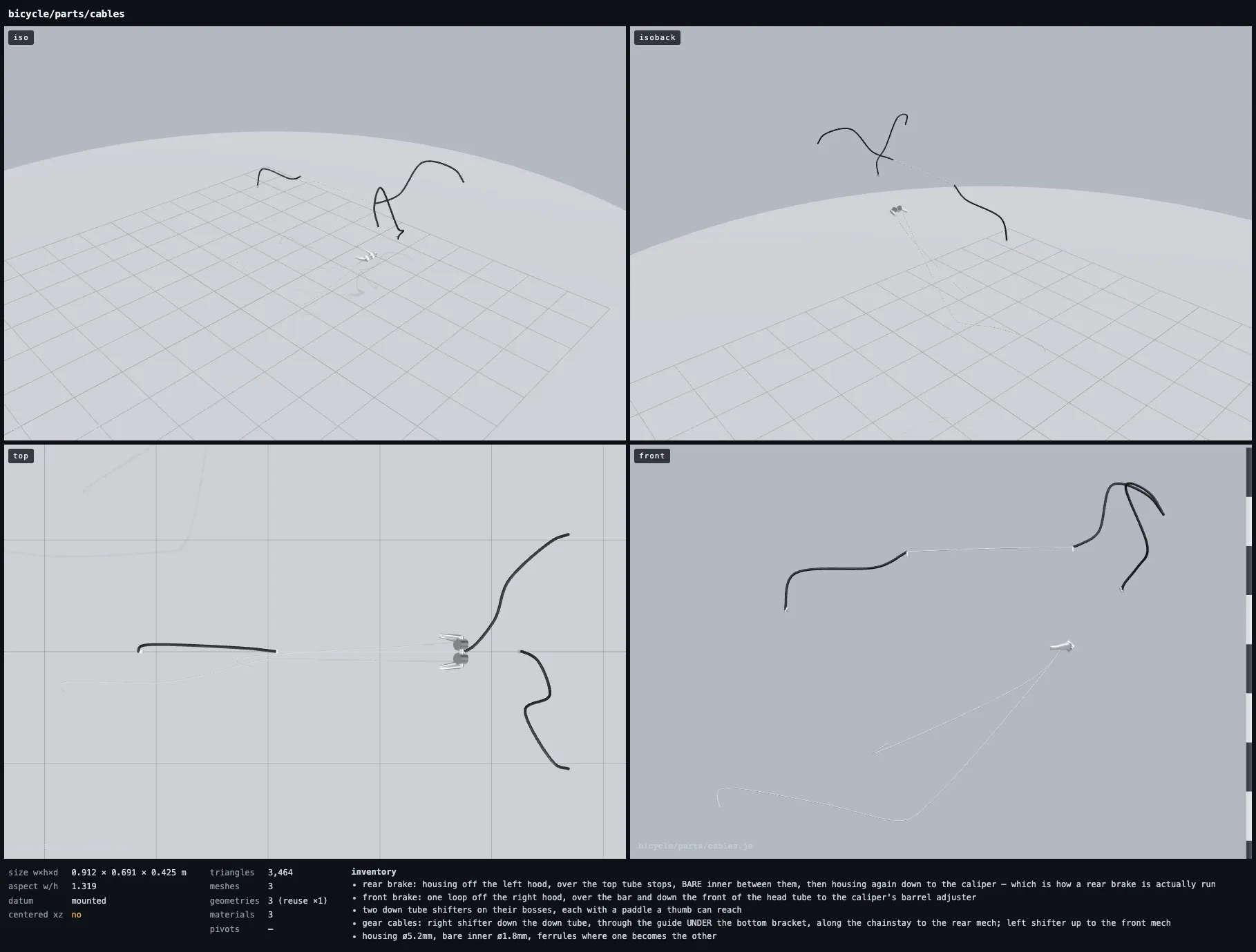
线缆单独看很轻,但它最能暴露组件之间有没有说同一种坐标语言。
线缆没有自己决定刹把和夹器在哪里。它从座舱读取 P.cableOut,从车架读取 P.topStopFront、P.topStopRear 和刹车座。上管两只线管座之间只走裸露内线,外管在端点处停下;这条很小的区别会让车从“有几条黑线”变成真正接好的刹车系统。
const run = (points, radius, segments = 30) =>
  taperedTubeGeo(points, [radius, radius], { seg: segments, radial: 7 });

const [ttx, tty] = P.topDir;
const ttUp = [-tty, ttx];
const stopFront = [
  P.topStopFront[0] + ttUp[0] * 0.0165,
  P.topStopFront[1] + ttUp[1] * 0.0165,
  0,
];
const stopRear = [
  P.topStopRear[0] + ttUp[0] * 0.0165,
  P.topStopRear[1] + ttUp[1] * 0.0165,
  0,
];

housings.push(run([
  [P.cableOut[0], P.cableOut[1], -HALF],
  [P.cableOut[0] - 0.105, P.cableOut[1] + 0.062, -HALF * 0.62],
  stopFront,
], CABLE.housingR, 40));
wires.push(run([
  stopFront,
  [(stopFront[0] + stopRear[0]) / 2, (stopFront[1] + stopRear[1]) / 2 + 0.0015, 0],
  stopRear,
], CABLE.wireR, 8));
辐条和链条要像零件,也要像像素
64 根辐条如果做成 64 个普通 Mesh,会平白多出 64 次 draw call。这里只造一根五边圆柱,再把每根辐条的矩阵写进 InstancedMesh。三交叉编法由花鼓孔位和轮圈孔位的角度差算出来。
const spokeGeo = new THREE.CylinderGeometry(0.00095, 0.00080, 1, 5);
const spokes = new THREE.InstancedMesh(spokeGeo, spokeMaterial, count);

for (let i = 0; i < count; i++) {
  const from = flangePoint(i);
  const to = rimPoint(i, { cross: 3 });
  const dir = to.clone().sub(from);
  const q = new THREE.Quaternion().setFromUnitVectors(UP, dir.clone().normalize());
  const mid = from.clone().addScaledVector(dir, 0.5);
  spokes.setMatrixAt(i, new THREE.Matrix4().compose(
    mid, q, new THREE.Vector3(1, dir.length(), 1)
  ));
}
spokes.instanceMatrix.needsUpdate = true;
真实直径在这个机位上不到一个像素,所以辐条略微加粗。这里追求的是稳定的细线,不是游标卡尺上的胜利。链条则不能偷成一根黑管:近看时,滚子和交替的内外链板正是“链条”这个读法。
动画只认曲柄相位
传动系统没有五套各跑各的速度。每帧只累加曲柄相位,其他转动从它推导。脚踏反向抵消父级旋转,所以始终保持水平;链条走过的距离就是相位乘牙盘半径。
let phase = 0;

function drive(dt) {
  phase += dt * (cadence / 60) * Math.PI * 2;
  cranks.rotation.z = -phase;
  pedals.forEach((pedal) => { pedal.rotation.z = phase; });

  chain.userData.advance(phase * chainringRadius);
  rear.rotation.z = front.rotation.z = -phase * gearRatio;
  cassette.rotation.z = -phase * gearRatio;
}
最后才处理展台:浅灰地面、软阴影、稍长的镜头和可以环绕的相机。镜头不是来替几何遮丑的,它只是检查前面的数学有没有落到正确的位置。把相机转到正面,两只轮胎仍在一条线上,这辆车才算完成。
A bicycle is well suited to modelling in code. Its shape is not a pile of parts that happen to line up. The wheelbase places the axles, the chainstay places the bottom bracket, and the head angle and rake place the fork. Once those relationships are written as mathematics, Three.js only has to draw the result.
There is no imported model in this bicycle. The frame, rims, spokes, chain, and even the brake cables are Three.js geometry. The complete source is in Makone; the excerpts below keep only what each step needs.
The first version began with two circles and a handful of CylinderGeometry objects. Ten minutes later it looked like a bicycle in profile. Turned toward the camera, the wheels no longer shared a centreline and the fork ran through the hub. The dimensions were scattered across dozens of unrelated position.set() calls.
The fix was to reverse the order: calculate points first, draw shapes second.
Write the bicycle as points
The scene uses metres throughout. The rear axle is the datum, and axle height equals the rolling radius. The front axle follows from the wheelbase. Even the bottom bracket is calculated from chainstay length and bottom-bracket drop rather than placed by eye.
const GEO = {
  wheelbase: 1.005,
  drop: 0.070,
  chainstay: 0.412,
  headAngle: 73,
  rake: 0.047,
  forkLen: 0.372,
};

const P = {};
P.rearAxle = [0, wheelR];
P.frontAxle = [GEO.wheelbase, wheelR];
P.bbY = wheelR - GEO.drop;
P.bbX = Math.sqrt(GEO.chainstay ** 2 - GEO.drop ** 2);
P.bb = [P.bbX, P.bbY];

const a = THREE.MathUtils.degToRad(GEO.headAngle);
const axisUp = [-Math.cos(a), Math.sin(a)];
const rakeDir = [Math.sin(a), Math.cos(a)];
P.crown = [
  P.frontAxle[0] + axisUp[0] * GEO.forkLen - rakeDir[0] * GEO.rake,
  P.frontAxle[1] + axisUp[1] * GEO.forkLen - rakeDir[1] * GEO.rake,
];
Those points become the model’s interface. The frame and crankset both read P.bb; the wheel, cassette, and derailleur all read P.rearAxle. Change the wheelbase and the assembly moves together. You do not find a brake caliper stranded at its old coordinates.
A head-on view is unforgiving. Models that pass as bicycles in profile tend to reveal every guessed offset here.
A tube only needs two endpoints
The basic frame tool is not a “top tube” or a “down tube.” It is simply a tube from A to B. A Three.js cylinder starts along the Y axis, so the helper finds the direction and midpoint, then rotates the geometry into place.
function tubeBetween(a, b, r0, r1 = r0, segments = 16) {
  const A = new THREE.Vector3(...a);
  const B = new THREE.Vector3(...b);
  const dir = B.clone().sub(A);
  const mid = A.clone().addScaledVector(dir, 0.5);

  const geometry = new THREE.CylinderGeometry(
    r1, r0, dir.length(), segments, 1, false
  );
  geometry.applyQuaternion(
    new THREE.Quaternion().setFromUnitVectors(
      new THREE.Vector3(0, 1, 0), dir.clone().normalize()
    )
  );
  geometry.translate(mid.x, mid.y, mid.z);
  return geometry;
}

painted.push(
  tubeBetween(P.headBottom, P.headTop, 0.0175),
  tubeBetween(P.topAtSeat, P.topAtHead, 0.0143, 0.0136),
  tubeBetween(P.bb, P.downAtHead, 0.0159, 0.0146),
  tubeBetween(P.bb, P.seatTop, 0.0143),
);
The chainstays and fork blades bend slightly, so TubeGeometry follows three or four control points and tapers along the path. Small parts can wait. Turn the model through four angles first and check the silhouette, ground clearance, and intersections.
Five assemblies, one set of mounting points
The bicycle is divided into frame, wheel, drivetrain, cockpit, and cables. The boundary is physical: if it can come off a real bicycle, it should be possible to build it on its own in code. The modules do not guess their own positions. They all read P from params.js, so there is only one answer for the bottom bracket, rear axle, top of the head tube, and brake mounts.
const bike = new THREE.Group();
bike.add(buildFrame(), buildDrivetrain(), buildCockpit(), buildCables());

const rear = buildWheel();
const front = buildWheel();
front.position.x = GEO.wheelbase;
bike.add(rear, front);

// Build forward from the rear axle, then centre the complete object.
bike.position.x = -GEO.wheelbase / 2;
scene.add(bike);
Frame: tubes do not merely meet “somewhere around here”
On its own, the frame has nowhere to hide the fork curve, rear-triangle clearance, or caliper placement.
Every tube in the main triangle joins two solved points. The stays need to clear the tyre and chainrings, so three control points bow them outward and taper them back in. At the end, geometries with the same material are merged into one mesh. Tiny lugs, cable stops, and fittings do not each consume a draw call.
const V = (xy, z = 0) => [xy[0], xy[1], z];
const painted = [], chrome = [], liners = [], blacks = [];

painted.push(
  tubeGeo(V(P.headBottom), V(P.headTop), p.tubeHead, p.tubeHead, 20),
  tubeGeo(V(P.topAtSeat), V(P.topAtHead), p.tubeTop, p.tubeTop * 0.95, 18),
  tubeGeo(V(P.bb), V(P.downAtHead), p.tubeDown, p.tubeDown * 0.92, 18),
  tubeGeo(V(P.bb), V(P.seatTop), p.tubeSeat, p.tubeSeat, 18),
);

for (const [geos, mat, parent] of [
  [painted, paint, g], [chrome, chromeMat, g],
  [liners, gold, g], [blacks, dark, g],
]) {
  const mesh = new THREE.Mesh(merge(geos), mat);
  mesh.castShadow = mesh.receiveShadow = true;
  parent.add(mesh);
}
Wheels: build twice, generate geometry once
The front view reads the lacing; the top view checks that rim, hub, and tyre share an axis.
buildWheel() runs twice, but the module caches the rim, tyre, hub, and spoke data. Both wheels share buffers and retain only their own position and rotation. Spoke matrices go into an InstancedMesh; otherwise all those hairlines would become a long list of separate meshes.
let CACHE = null;

function geos(p) {
  if (CACHE) return CACHE;
  const rIn = p.rimR - p.rimDepth;
  const rOut = p.rimR;
  const halfWidth = p.rimW / 2;
  const V = (r, y) => new THREE.Vector2(r, y);

  const body = [
    V(rOut - 0.0165, -halfWidth * 0.84),
    V(rIn + 0.0030, -halfWidth * 0.30),
    V(rIn, -halfWidth * 0.42),
    V(rIn, halfWidth * 0.42),
    V(rIn + 0.0030, halfWidth * 0.30),
    V(rOut - 0.0165, halfWidth * 0.84),
  ];

  CACHE = {
    body: new THREE.LatheGeometry(body, 72).rotateX(Math.PI / 2),
    tyre: new THREE.TorusGeometry(p.rimR + p.tyreR * 0.62, p.tyreR, 16, 96),
    lace: lacing(p),
  };
  return CACHE;
}

const G = geos(p);
wheel.add(
  new THREE.Mesh(G.body, materials.rim),
  new THREE.Mesh(G.tyre, materials.gum),
  instanced(G.lace.spokes, materials.spoke),
  instanced(G.lace.nipples, materials.brass),
);
Drivetrain: draw the mechanical profile before making it move
The drive side easily collapses into a metallic tangle. Isolated, the chainrings, chain line, and derailleur layers become readable.
A chainring is not a disc with a toothed texture. Its outer path alternates radius according to tooth count, while the middle is cut for the bore and windows. ExtrudeGeometry gives that path thickness, so spider, teeth, and chain remain distinct at close range.
function ringGeo(rOuter, teeth, thickness, { rBore, windows = 5 }) {
  const shape = new THREE.Shape();
  const toothDepth = Math.min(rOuter * 0.10, ((Math.PI * rOuter) / teeth) * 0.9);

  for (let i = 0; i < teeth * 2; i++) {
    const angle = (i / (teeth * 2)) * Math.PI * 2;
    const radius = i % 2 ? rOuter - toothDepth : rOuter;
    const [x, y] = [Math.cos(angle) * radius, Math.sin(angle) * radius];
    if (i) shape.lineTo(x, y); else shape.moveTo(x, y);
  }
  shape.closePath();

  const bore = new THREE.Path();
  bore.absarc(0, 0, rBore, 0, Math.PI * 2, true);
  shape.holes.push(bore);

  const r0 = rBore + (rOuter - toothDepth - rBore) * 0.20;
  const r1 = rBore + (rOuter - toothDepth - rBore) * 0.82;
  for (let i = 0; i < windows; i++) {
    const centre = (i / windows) * Math.PI * 2 + 0.30 + Math.PI / windows;
    const half = (Math.PI / windows) * 0.72;
    const window = new THREE.Path();
    window.absarc(0, 0, r1, centre - half, centre + half, false);
    window.absarc(0, 0, r0, centre + half, centre - half, true);
    shape.holes.push(window);
  }

  return new THREE.ExtrudeGeometry(shape, {
    depth: thickness,
    bevelEnabled: false,
  });
}
Cockpit: bar and tape must share one curve
The saddle and bar sit far from the frame centre, so a small offset changes the posture of the whole bicycle.
The drop bar is mirrored left and right, with each side defined by a list of control points. The tape cannot follow a second “close enough” spline; it would dive into the alloy through the bends. The bar path is sampled once, then the same point list is sliced for the taped section.
const [bx, by] = P.barCentre;
const half = p.barW / 2;

for (const sz of [-1, 1]) {
  const points = [
    [bx, by, 0],
    [bx, by, sz * half * 0.42],
    [bx - 0.004, by - 0.002, sz * half * 0.80],
    [bx + 0.022, by - 0.008, sz * half * 0.97],
    [P.hoodAt[0], P.hoodAt[1], sz * half],
    [bx + p.barReach, by - p.barDrop * 0.55, sz * half],
    [bx + p.barReach * 0.62, by - p.barDrop, sz * half],
    [bx + p.barReach * 0.04, by - p.barDrop * 0.96, sz * half],
  ];

  const spine = new THREE.CatmullRomCurve3(
    points.map((q) => new THREE.Vector3(...q)), false, 'centripetal',
  ).getSpacedPoints(64);

  bright.push(taperedTubeGeo(spine,
    [p.barR * 1.06, p.barR * 1.02, p.barR, p.barR, p.barR, p.barR, p.barR, p.barR],
    { seg: 52, radial: 12 }));
  taped.push(taperedTubeGeo(spine.slice(11),
    [p.barR + 0.0020, p.barR + 0.0026, p.barR + 0.0026,
      p.barR + 0.0026, p.barR + 0.0026, p.barR + 0.0022],
    { seg: 54, radial: 14 }));
}
Cables: connect parts that already exist
Cables are visually light, but they are the quickest test of whether the other assemblies speak the same coordinate language.
The cable module does not decide where a lever or caliper sits. It reads P.cableOut from the cockpit and P.topStopFront, P.topStopRear, and the brake mounts from the frame. Between the two top-tube stops, only the bare inner wire continues. That small break turns “some black curves” into a brake system that has actually been connected.
const run = (points, radius, segments = 30) =>
  taperedTubeGeo(points, [radius, radius], { seg: segments, radial: 7 });

const [ttx, tty] = P.topDir;
const ttUp = [-tty, ttx];
const stopFront = [
  P.topStopFront[0] + ttUp[0] * 0.0165,
  P.topStopFront[1] + ttUp[1] * 0.0165,
  0,
];
const stopRear = [
  P.topStopRear[0] + ttUp[0] * 0.0165,
  P.topStopRear[1] + ttUp[1] * 0.0165,
  0,
];

housings.push(run([
  [P.cableOut[0], P.cableOut[1], -HALF],
  [P.cableOut[0] - 0.105, P.cableOut[1] + 0.062, -HALF * 0.62],
  stopFront,
], CABLE.housingR, 40));
wires.push(run([
  stopFront,
  [(stopFront[0] + stopRear[0]) / 2, (stopFront[1] + stopRear[1]) / 2 + 0.0015, 0],
  stopRear,
], CABLE.wireR, 8));
Make thin parts read without wasting draw calls
Sixty-four spokes as ordinary meshes would add sixty-four draw calls. One five-sided cylinder is enough; every spoke transform is stored in an InstancedMesh. Three-cross lacing comes from the angle between a flange hole and its corresponding rim hole.
const spokeGeo = new THREE.CylinderGeometry(0.00095, 0.00080, 1, 5);
const spokes = new THREE.InstancedMesh(spokeGeo, spokeMaterial, count);

for (let i = 0; i < count; i++) {
  const from = flangePoint(i);
  const to = rimPoint(i, { cross: 3 });
  const dir = to.clone().sub(from);
  const q = new THREE.Quaternion().setFromUnitVectors(UP, dir.clone().normalize());
  const mid = from.clone().addScaledVector(dir, 0.5);
  spokes.setMatrixAt(i, new THREE.Matrix4().compose(
    mid, q, new THREE.Vector3(1, dir.length(), 1)
  ));
}
spokes.instanceMatrix.needsUpdate = true;
At this camera distance, a true spoke is narrower than one pixel, so the rendered diameter is slightly exaggerated. The goal is a stable hairline, not a caliper reading. The chain cannot get away with being a black tube: once the camera comes close, rollers and alternating side plates are what make it read as a chain.
Drive everything from crank phase
The drivetrain does not maintain five independent speeds. Each frame advances one crank phase and derives every other motion from it. Pedals counter-rotate against their parent and stay level. Chain travel is simply crank angle multiplied by chainring radius.
let phase = 0;

function drive(dt) {
  phase += dt * (cadence / 60) * Math.PI * 2;
  cranks.rotation.z = -phase;
  pedals.forEach((pedal) => { pedal.rotation.z = phase; });

  chain.userData.advance(phase * chainringRadius);
  rear.rotation.z = front.rotation.z = -phase * gearRatio;
  cassette.rotation.z = -phase * gearRatio;
}
The studio comes last: a pale floor, soft shadows, a moderately long lens, and an orbit camera. The camera is not there to hide weak geometry; it checks whether the mathematics landed in the right place. Turn it head-on. If both tyres still sit on one line, the bicycle is finished.